|
Winamp LED Visualization
Page: 3/5 Now your board is essentially done. Next we will move on to soldering into the DB25 connector. This process is fairly simple. Make sure your solder points are strong because this part will receive a bit of punishment if you are switching between the meter and a printer, or if you want to unplug it at night (like me). You should always have a hood for your connector too. This will prevent stress on 1 particular solder point and will also prevent short circuits. NOTE: If you are using CAT5, be warned that it is extremely hard to strip unless you have uber1337 wire stripping skills with your fingernails, a knife, or some special order wire strippers. Also, you will need 1 additional wire for your ground. On the DB25 connector, we will be working with pins 2-9 and 25. The bottom channel will go on pin 2, the next on 3, etc up to 9. The ground will go on pin 25. See the diagram below for pin locations. 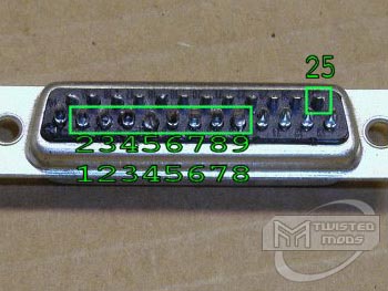 Now we need to prep our cable for soldering. When using CAT5, you can separate the pairs into pairs for your LED colors (assuming you used 4 colors). This worked great for me because I could use blue for blue, green for green, orange for yellow, and brown for red. 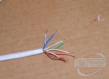 I used the color-white for the lower LED of that color, and the solid for the upper LED. Make sure you put your hood on BEFORE soldering.  Now flip the connector and solder your ground. 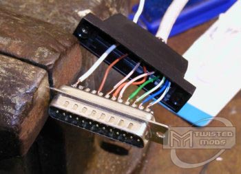 Close the hood, add a zip tie, and you're good to go. You will want to bound the wires together. With CAT5, the shielding works, and I attached the ground with electrical tape.  < Previous Page 2/5 || Next Page 4/5 > |
||||||||||||||||||||


